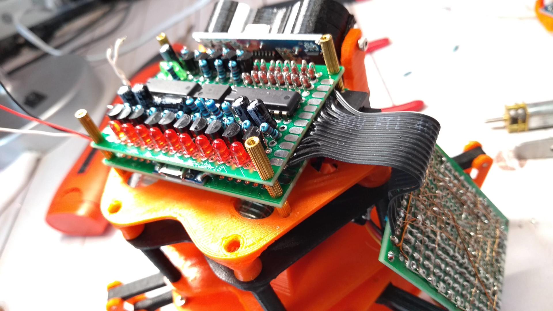
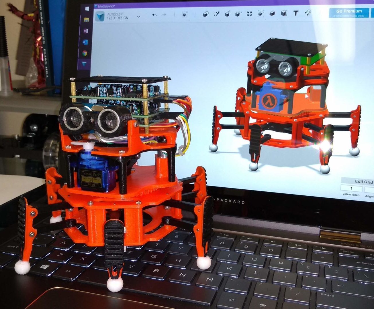
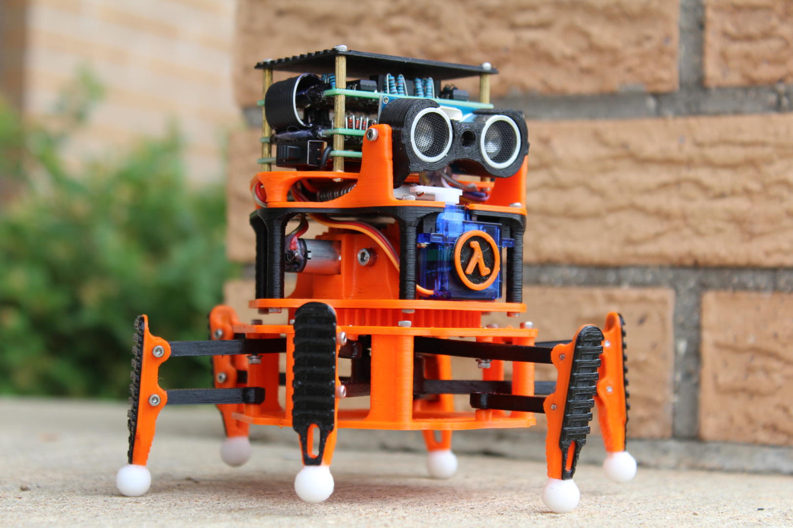
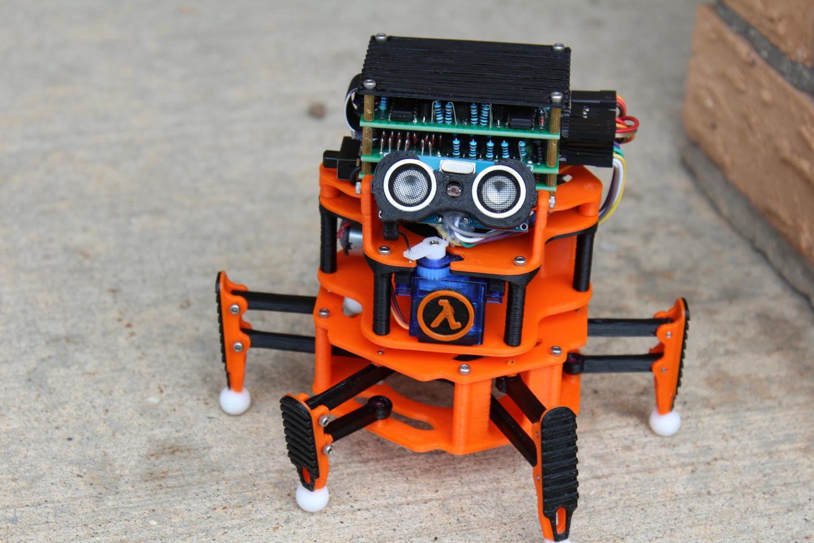
Based off my larger walker, the Pathfinder Mini is a cost-reduced version which requires far fewer parts, much less plastic, and is a bit more simple to build. I will be releasing the plans for it as soon as I can, and considering the reduced part count, I may be able to sell complete kits instead of my usual plans or plastic-only kits.
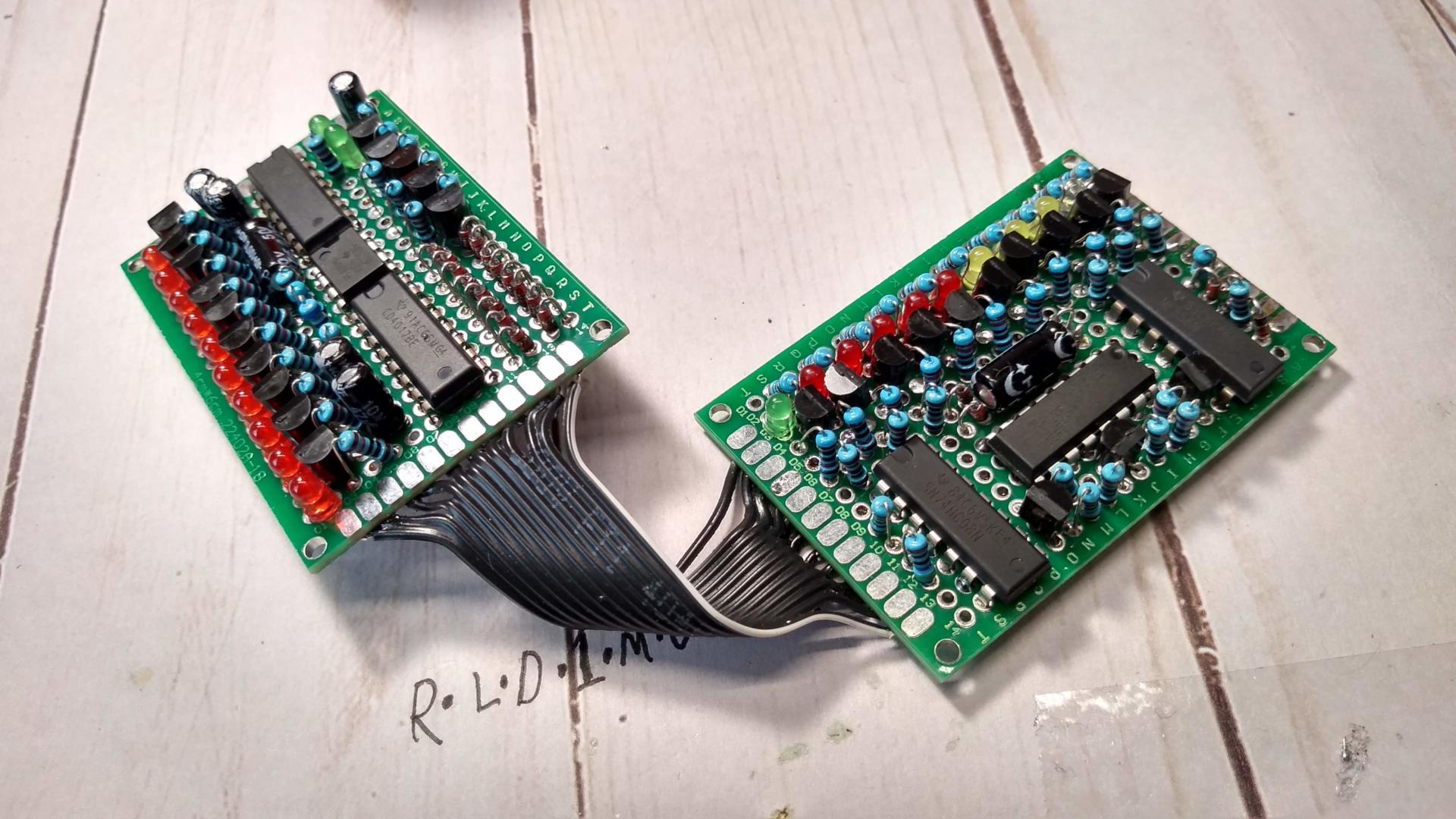
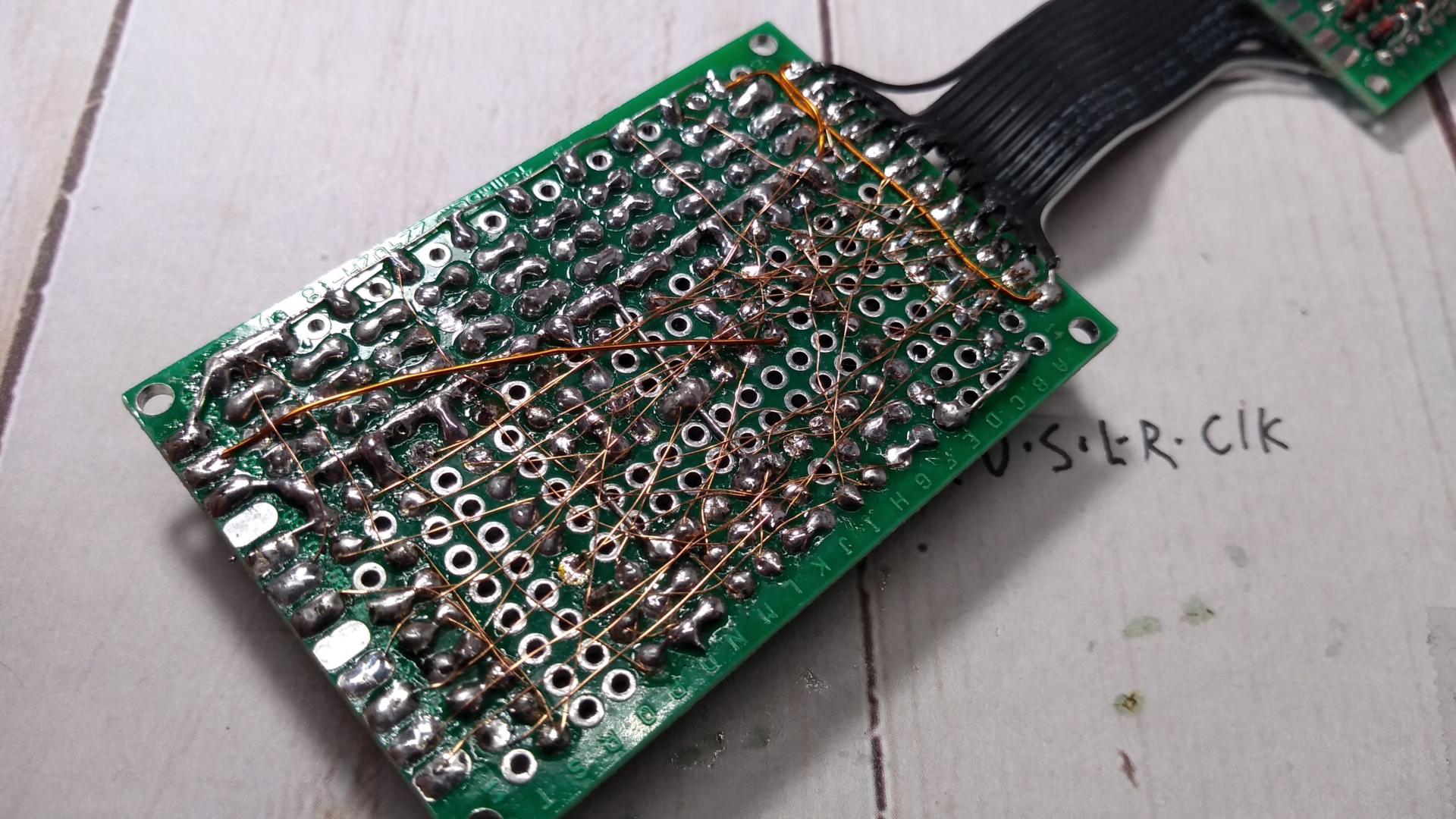
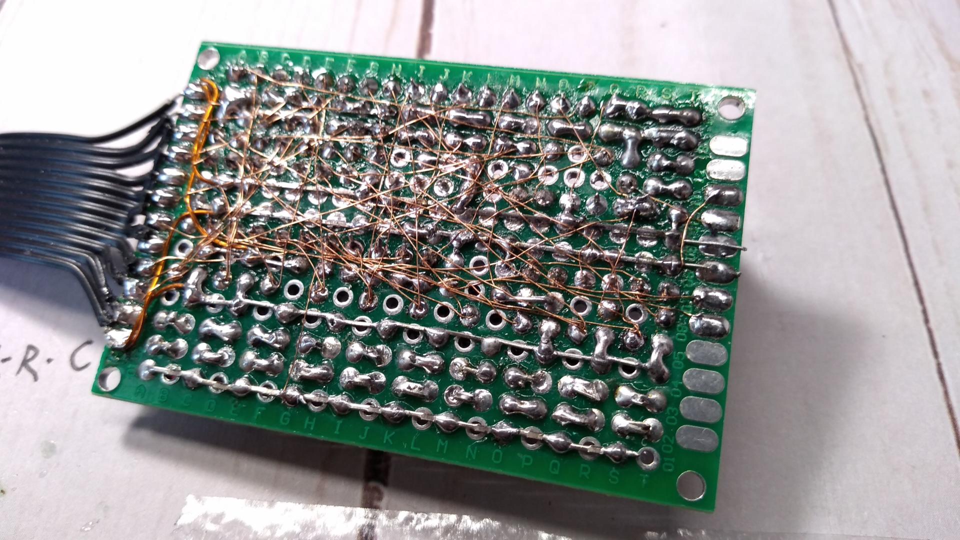
If it were economically feasible, I would also like to make a batch of circuit boards to include with the kit. As of right now, it's too complex to build in point-to-point wiring, but a PCB with proper traces would be nice. I'd have to ditch the LEDs as a cost saving measure though as well. Or, you know, I could just use a microcontroller like a sane person.
This circuit was really just a fun project to prove I could build this idea from my head into an actual working robot. It does work quite well, and schematics and an explanation of the design is listed below.
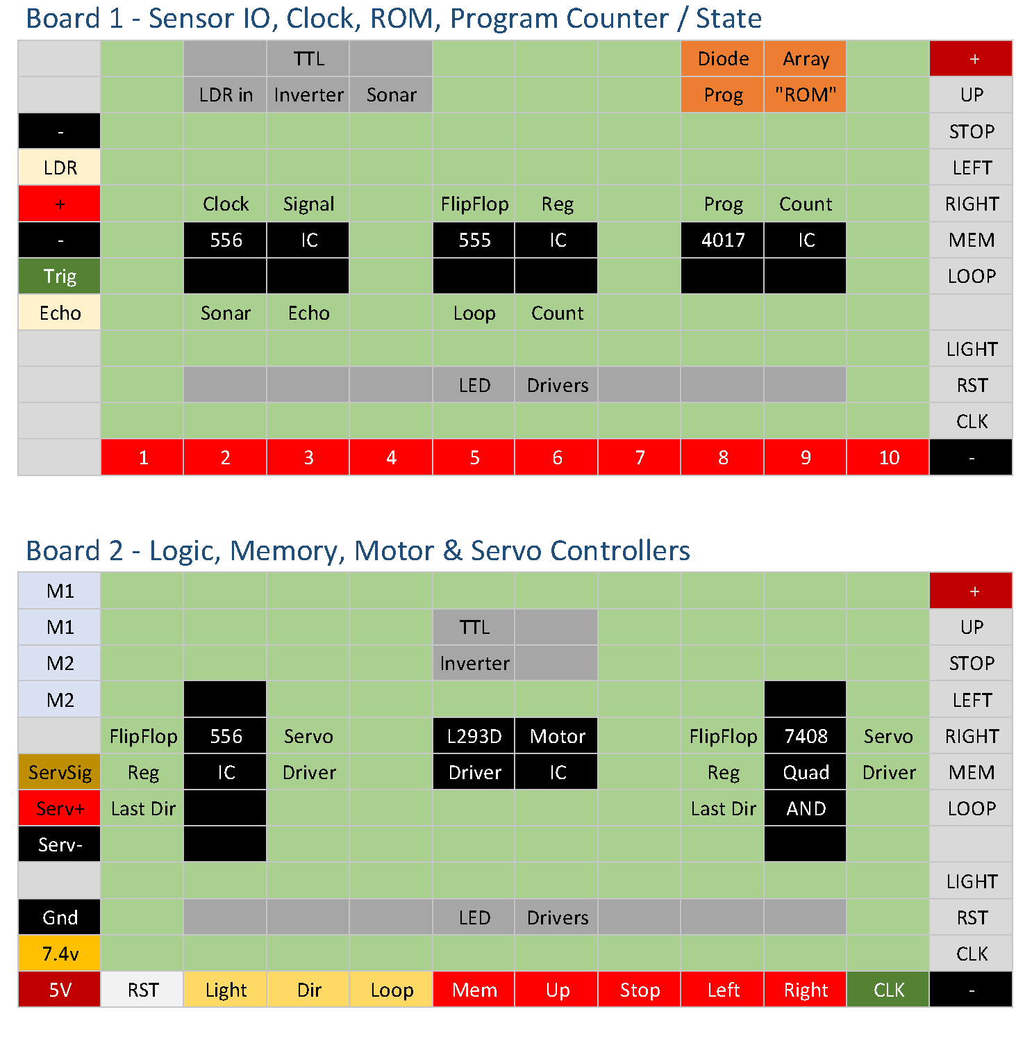

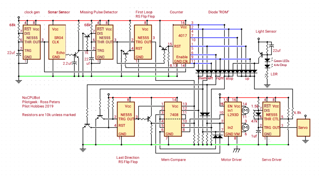
Clock Gen
Astable 555 timer which generates the clock signal for SR04 Sonar Sensor and 4017 Counter.
Sonar Sensor
HC-SR04 Sonar Sensor. A clock pulse triggers a sonar ping. Pulse width on echo pin is proportional to echo time.
Missing Pulse Detector
The echo pin from sonar seamlessly refreshes the monostable 555 timer, keeping the output high. A resistor-capacitor circuit snubs out short pulses from close objects, causing the output of the 555 to go low. This causes a reset for the “Counter” and “First Loop” circuits.
First Loop
RS flip-flop “register” using a 555. Upon reset, the output is set high. The last output from the counter will set the output low
Counter
“Program Counter” using a 4017. Each clock pulse pulls one of 10 pins high, in sequence. A reset brings the output back to 0.
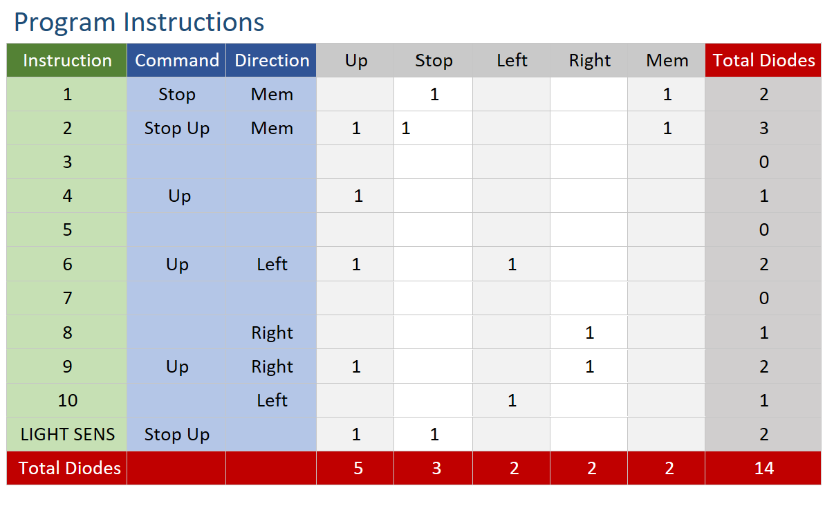
Diode “ROM”
Diode logic is used to hard-wire program instructions to each step of the counter. These instructions consist of “Left, Right, Stop, Up, and Load MEM”.
Light Sensor
Functions outside the program loop. Injects instructions for “Stop” and “Up” when light is above a threshold. Not strictly necessary, but adds a bit of interactivity.
Last Direction
RS Flip-flop “Register”. Retains the last direction executed from ROM after a reset.
MEM Compare
Combinational logic to determine the results of the MEM instruction. If the “First Loop” register is true, the “Last Direction” register is interpreted as either a “Left” or “Right” instruction. This provides obstacle avoidance when a reset is triggered by the sonar sensor, and is ignored in subsequent loops. Also only allows STOP instruction on first loop.
Motor Driver
A L293D motor driver circuit. I recommend capacitors on the motor outputs.
Servo Driver
A 555 timer in astable mode. The output is pulse width modulated via a voltage on pin 5, resulting in basic servo control for head tilt.